Description for invention (patented) entitled:
Device for automatic releasing of seatbelts on road vehicles and boats
Description
The present invention relates to a device for automatic releasing of seatbelts on road vehicles and boats. It must be understood however that such device, relatively with the automatic release of safety belts, may also be associated with other types of systems suitable for carrying people.
There are known devices for the automatic release of safety belts which are provided with a sensor for the water (generally a tablet of water-soluble salt) which, in contact with the water itself, releases a firing pin spring that releases the belts.
Although the operation of this system is satisfactory, it allows the automatic release only in cases that apparatus is in direct contact with the water; this allows to use only in cases of total immersion of the vehicle or in the case of overturning or sinking of boats.
The object of the present invention is to provide a device for automatic release capable of being used in any type of accident and not limited to the case where will come in contact with the water.
This problem is solved by a device for automatic release which includes:
– an electronic control unit connected to a backup battery capable of timing and controlling the operation of the device;
– a pneumatic solenoid valve;
– a motion detector,
– an air compressor with a tank including the adequate power reserve (air pressure) to move one or more pneumatic cylinders used in the invention;
– One or more pneumatic cylinders (one for each belt to release)with adequate power to allow pressing the hook sealing of the safety belt to which it is connected.
Additional details, characteristics and advantages of the present invention will be apparent from the following description of a preferred design thereof, given by way of non-limiting example, with reference to the included drawings in which:
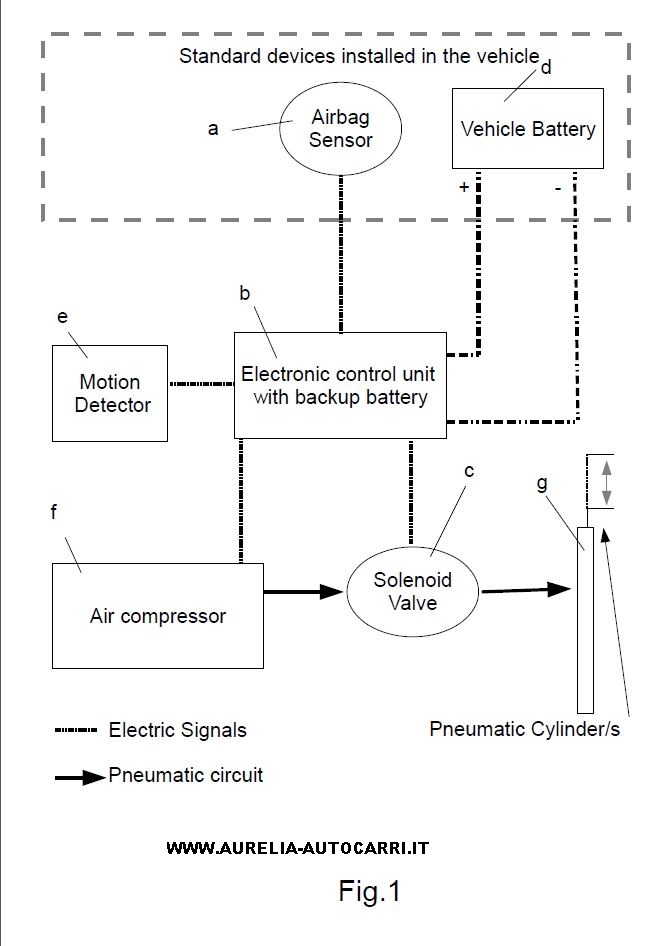
- Figure 1 shows a block diagram relating to the invention, specifying also the devices which are and must already be present in the vehicle or boat;
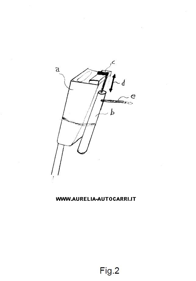
- Figure 2 shows a possible connection of the pneumatic cylinder to the hook of the belt; such connection is purely indicative and not limiting, as defined in claims.
With reference to Figure 1 there will be described the operation of the device in case of accident of the vehicle or boat by following sequence of steps:
Step 1 – Detection of the accident by airbag sensor [a] already present in the vehicle. The electric signal coming from the accident sensor reaches the ECU (Electronic Control Unit) [b] of the invention which immediately activates the compressor [f], fitted with pressure switch, that pumps air in their tank (to be considered that the solenoid valve [c] that is connected to the pneumatic circuit at the compressor outlet is normally closed).
The compressor is powered by the backup battery included in the ECU [b] and is kept charged by the battery [d] during normal use of the vehicle or boat, while in case of an accident this battery provides enough power to the system also in the event lose or break the electrical circuit of the vehicle due to the accident itself.
Step 2 – Motion detection by the motion detector [e].
During the accident the motion sensor [e] sends an electrical signal of motion detection. All the time in which the control unit receives this signal the solenoid valve [c] will be left closed and the compressor will remain on (keeping air pressure in its tank).
Step 3 – End of motion detection.
When the incident will be concluded and the vehicle or boat will be rest the motion sensor [e] no longer sends the electrical signal to the control unit. The control unit [b] calculate if it is past a time sufficient to gain the high pressure inside the air compressor tank, in the positive case, will open the solenoid valve [c],in the negative case wait for the time to pump the air in in the tank of the compressor and then open the solenoid valve [c].
Step 4 – Uncoupling of safety belts.
The opening of the solenoid valve [c] pump pressure in the pneumatic circuit until the pneumatic cylinder [g], placed on support of the hook (Figure 2),due to the compressed air coming from the tank of the compressor, executes a movement of the hook connected to the cylinder itself (Figure 2) from top to bottom allowing the release button of the seat belt to be pressed. In this way, the passenger is released automatically from the safety belt.
With reference to Figure 2 will be described a possible connection of the pneumatic cylinder of the invention to the hook of the safety belt:
The pneumatic cylinder [b] is mounted to the hook of the seat belt [a]; the movable pin of the pneumatic cylinder consists of a inverted L cylinder [c] so that in rest condition (with the pneumatic circuit at ambient pressure) does not interfere with the release manual button. When the pneumatic circuit [e] is put under pressure (step 4 of the description of operation) the L cylinder performs a downward movement [d] able to press the button of the hook and consequently free the seat belt.
At the above described device a skilled engineer, in order to satisfy further and contingent needs, may effect several further modifications and variants, all however comprised within the scope of the present invention, as defined by the appended claims.
Download : Description_Device for automatic releasing of seatbelts